Practical Electronics is designed to familiarize students with the basic concepts and components of electronic circuitry and equipment. This is accomplished through theoretical study of electricity and completion of practical labs. Throughout the duration of the class, students will learn the proper use of electronic test equipment, how to read and analyze electrical diagrams, and perform selected experiments related to the lessons presented in class. No initial lab fee is required, but students will be required to cover costs associated with any individual projects completed in class to take home.
Maglev Project
|
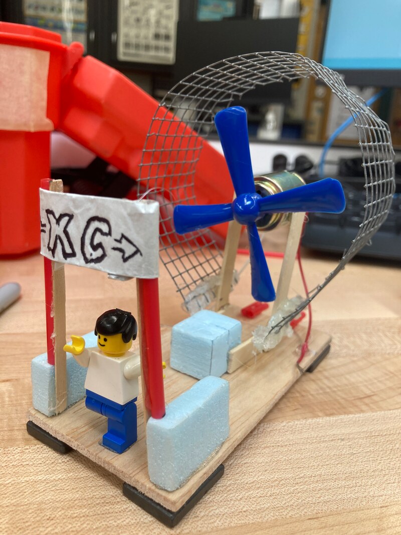
What: In this project, we were assigned to make a Maglev Vehicle that will move from point A to point B in the model maglev track three times without stopping.
How: For this project I wanted to make a Maglev vehicle that light weighted and simple, but fast. So I first made a rectangle thin wood, I make sure the side is wide enough to balance on the track. Then I add my 4 magnets in the bottom on each corner of thin wood. Next, I put my focus on making the small DC motor with propeller to stand without adding a lot of weight in the wood. So I made a small box that would connect to crafting sticks and then I glued it to the DC motor. After that, I glued the wire on each side of the wood. lastly, it was working pretty well, and I add some design to my maglev vehicle just for fun. Why: We did this project to get a better understanding as to how Maglev Vehicles and trains work, and how friction can affect these vehicles. For example, we learned that we can use magnets to remove friction caused by contact with the ground, allowing us to make gained momentum, and accelerate faster. |

|
|
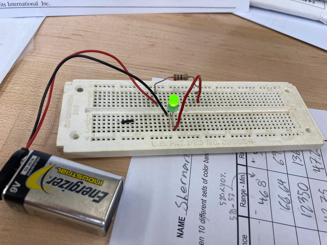
Lab 1 - LED Current IndicatorWhat: On this project I have to make a circuit on a circuit board using three components: a 9V battery, the LED, and the 100 ohms resistor, which are connected in series. In this lab you're going to learn how a resistor works.
How: In this circuit the current flows from the negative (black wire) of the battery to the positive (red wire) of the battery. The one side of the LED is connected to a 100 ohms resistor which helps to control the amount off current flows to the LED, so it doesn't kill the LED. Why: We did this lab to get a better understanding of how a resistor helps to control the current flowing through LED. We use the resistor so that the LED don't explode by itself. |
|
Lab 2 - Intro to Potentiometers/RheostatsWhat: The potentiometer helps to control the brightness of the LED by adjusting the potentiometer from one end to another, the resistance changes, producing a change in the amount in the current flowing in the cuicuit.
How: The electrons flow through from the negative wire of the battery, and travel to the lead of a 100 ohms of a resistor. Then the current go through the short lead (negative wire) of the LED, and going out to the positive lead (long wire) of the LED, the current then travels through the potentiometer giving you the power to control the brightness of the LED. Why: Doing this lab is important because it teaches you about potentiometer and how it works as a variable resistor in a circuit board. |

|
Lab 3 - Light Activated LEDWhat: The photocells is like resistor, but the light sensitive one. The more light hitting its surface, the lower its internal resistance. The less light hitting its surface, the greater the resistance.
How: In this circuit, the current flows from the negative wire of the battery to the positive wire of the battery, passing through the negative lead of the LED going out to the positive lead and through the photocell. The photocells is like reisistor, but the light sensitive one. The more light hitting its surface, the lower its internal resistance. The less light hitting its surface, the greater the resistance. Why: Doing this lab you will learn how a photocells works in a circuit and how you can use them. It is use in landscape lights and security in home. |

|
Lab 4 - Storage of ElectronsWhat: The capacitor is a device capable of storing energy in a form of an electric charge. Compared to a same size battery, a capacitor can store relatively large amounts of electricity, but useful enough for so many design. They have polarity, which means that they have a positive and a negative terminal and therefore care must be taken when connecting them to a circuit. They must be put in the right direction.
How: In this lab, when the battery is connected, the current flow in the circuit. the current goes from the negative terminal of the battery to the commonly charge where the capacitor at in the image shown. Then the current goes through the LED and 1K ohms of a resistor, causing the LED to turn on, and the other part goes to 1000 uF capacitor, which starts to charge. Once the uF capacitor is charge, the current stops flowing to it. Now when the battery is disconnected, the electrical energy stored in the capacitor flows in the current path, which keeps the LED illuminated until the capacitor completely discharges. Why: By doing this lab you will learn how a capacitor works and acts in a circuit. You will also observe the effect of a capacitor storing electrical energy. |

|
Lab 5 - Speaker ActionWhat: The speaker is an electromechanical device that produces a movement of its cone when the current is flowing through it. if the current flows in one direction through the speaker, the cone move in a certain direction. If the current flows in the opposite direction, the the cone moves in the opposite direction.
How: In this lab, we have a pretty simple looking circuit. The positive terminal of the battery is connected to one of the wire of the speaker while the other wire of speaker is disconnected. Then, a 10 ohms of a resistor is connected to the negative terminal the battery. Every time you touch the speaker wire to the resistor, the cone moves and produce a sound. Why: By doing this lab your going to observe how a speaker transforms electrical energy (current flowing through it) into sound waves. |

|
Lab 6 - Diode TesterWhat: A diode is a one-way gate. It allows current to flow through it in the circuit only when its anode is positive and its cathode is a negative.
How: As you can see in the picture shown the negative terminal is connected to the diode and goes through the 220 ohms resistor. Then, the current goes through short lead of the LED and going out to long lead of LED making it illuminate. When the diode is conected in the Diode Tester Circuit with its anode on positive point and its cathode on negative point, it allows current to flow through it, and therefore, the LED turns on. Why: By doing this lab, you will observe how a diode allows current to flow through it in one direction only. |

|
Lab 7 - SCR CheckerWhat: An SCR is a "diode with a difference." Like a diode, it has cathode and anode, and it allows current to flow through it at one direction only. Yet, unlike the simple diode, it has a gate electrode as well. The gate used to "triggered" the SCR into conduction. Only when the gate receives a positive voltage will the SCR conduct.
How: In this experiment, we know that the current flow from the negative terminal to positive terminal of the battery. When the gate of the SCR is touch by the disconnected wire in the image shown, you just applied a positive voltage to it. Therefore, the SCR starts to conduct causing current to flow from negative of the battery to the positive terminal. Passing through the SCR, the LED, and the 1k resistor. When the battery is disconnected, current stops flowing and the SCR turn off. To turn on the LED, the battery should connected because the SCR will be turn off until a positive voltage is again applied to its gate. Why: By doing this lab, you'll will learn how an SCR works and be able to build a useful SCR checker. |

|
Lab 8 - NPN Transistor CheckerWhat: Transistors are made from semiconductor materials such as Silicon or Germanium. Depending on how the transistor is constructed, it becomes an NPN or PNP type.
How: The schematic diagram shows the circuit of the transistor checker. It uses an NPN transistor. Its Collector receives a positive voltage from the battery through 220 ohms resistor and LED2. The emitter is connective directly to the negative terminal of the battery and the base receives a positive voltage from the positive terminal of the battery through 1k resistor, the push button, and LED1. Why: The purpose of this lab is to observe how an NPN transistor works as a current amplifier by controlling a large current (Collector Current) with a small current (Base Current). Also, know how to build a useful NPN Transistor Checker. |

|
Lab 9 - PNP Transistor CheckerWhat:
In this lab, we have to make a circuit that both controls an LED via a button, and at the same time controls another LED with the same button, but with a different amount of current. How: We used different resistors connected to the negative of the 8-Volt and hooked one up to each LED. We put a button in series with one of the LEDs, and connected the other end to the base of a PNP transistor. We hooked the collector of the transistor in series with the other LED, and the emitter to the positive of the 8-Volt battery. Why: We did this experiment for the same reason we did #8, except there is one difference; instead of hooking everything up the same way, but with a different transistor, the polarity of everything is inverted. This is because the polarity of the transistor is the opposite of the polarity of the transistor from #8. |

|
Lab 10 - Transistor Oscillator
|
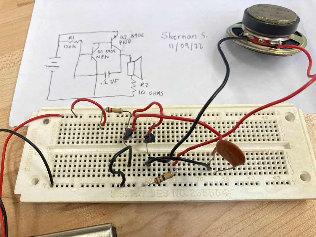
What: In this lab, we have to make a circuit that produces a slightly varying audio signal using transistors in a circuit.
How: We hooked up 2 transistors in a feedback-loop arrangement using a capacitor and resistors. This made the current to a speaker, which was hooked up to one of the transistors, turn on and off, producing a signal that, using the speaker, can be turned into a tone. Basically one transistor, by default, produces a value that is delayed by the capacitors and resistors, and once the capacitor reaches a high enough amount to trigger the other transistor to stop the first one, both lose power immediately and the cycle repeats. Why: We did this lab to learn how transistors work and can be used. Feedback loops are useful in a variety of scenarios, and are really important to understand for this reason. |
|
Lab 11 - Blinking LightWhat:
In this project, I had to make a circuit that makes an LED blink. How: We used a 555 IC Timer as an oscillator, using a capacitor and 3 resistors, to create an alternating high or low signal, which was connected to the LED. This caused the LED to blink, as the current flowing through it flowed and stopped on and off. By changing the value of the capacitor and/or resistors, you can change the frequency of the signal produced, due to the capacitor needing to reach a certain point to cause the 555 timer to change it's value, and the delay being different for each resistor and capacitor you use. Why: We did this lab to learn about one of the uses/modes of a 555 IC timer, and learn more about the functions of each pin on the chip. |

|
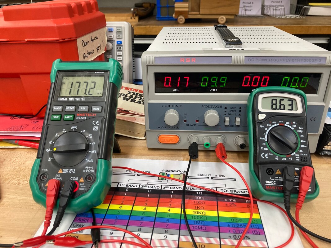
LAB 13: SAFETY, POWER SOURCES & METERS
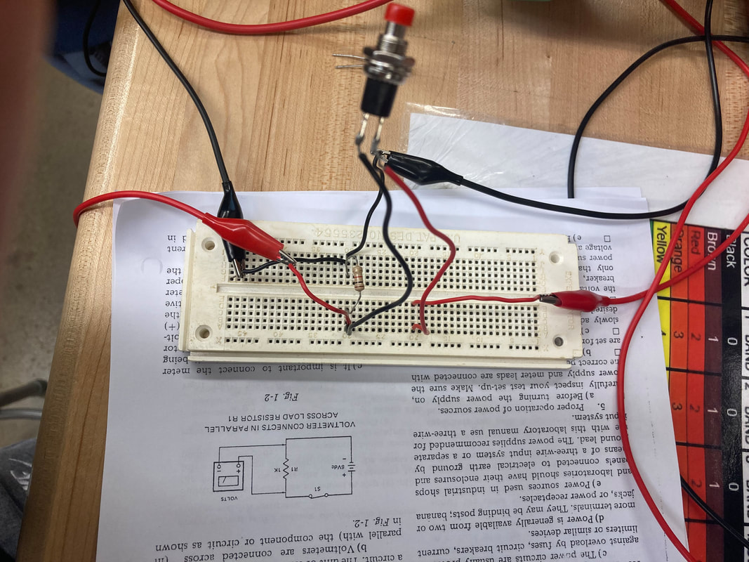
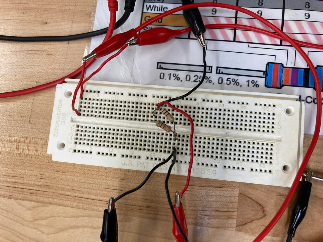
In this circuit we connect the voltmeters in a parallel across load 1k resistor.
|
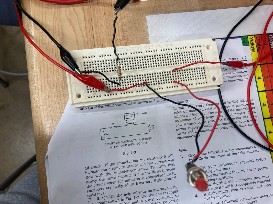
In this circuit we connect the voltmeters in a series across load 1K resistor.
|
What:
The purpose of this lab is to know the safety precautions when working with electronics circuits. We also, measure the electrical resistance of our body using the ohmmeter function of the Electronics VOM.
The resistance of my body was found to be 1.6 Mega-Ohms, or 1,600,000 ohms. This means that to get 0.1 amps of current flowing through my body, it would take 160KV, or 160,000 volts to force that current into my body, which means that 160KV has the power to kill me.
The resistance of my body was found to be 1.6 Mega-Ohms, or 1,600,000 ohms. This means that to get 0.1 amps of current flowing through my body, it would take 160KV, or 160,000 volts to force that current into my body, which means that 160KV has the power to kill me.
How:
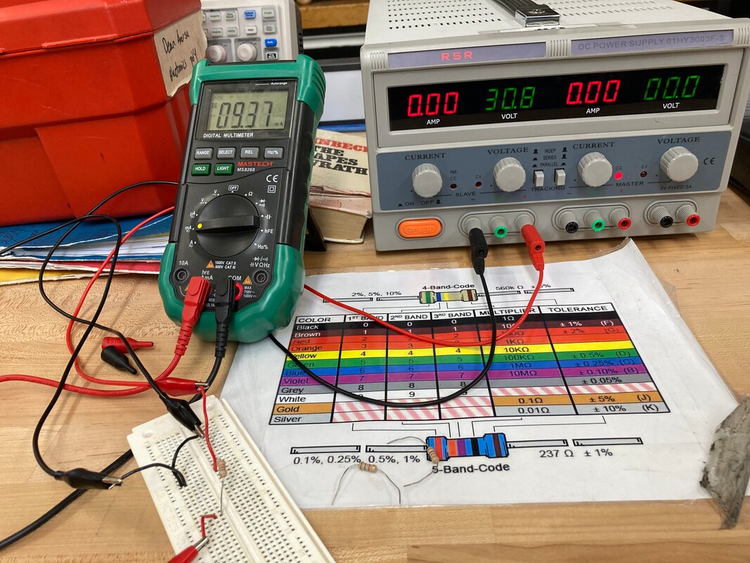
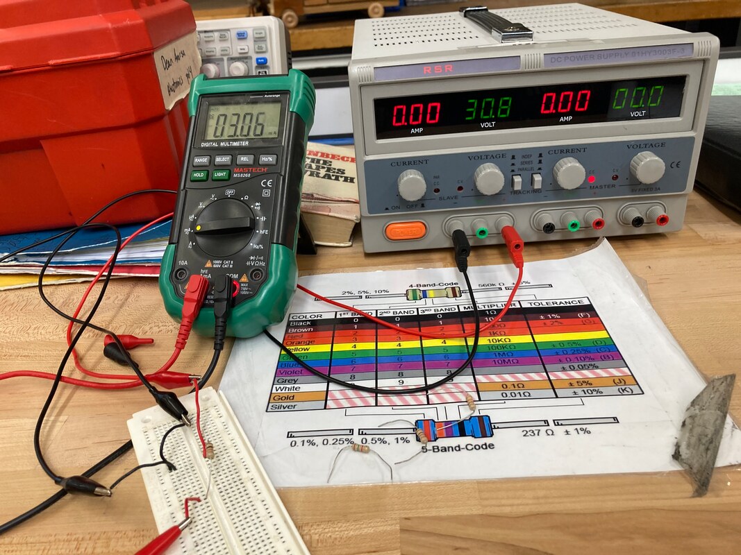
On both circuits we uses the DC Power Supply to apply voltage and find the current of each circuits. As you can see on the left image above we can see on the schematic that the digital multimeter measures the 1K ohm resistor, as the leads encompass it. When reading the resistance, the numbers proved this, reading about 998 ohms of resistance.
In the right image we see that the multimeter does not encompass our 1K Ohm resistor, meaning that, in theory, it could not detect the resistance from it. Running the numbers, that's precisely what it did. The circuit here is a series circuit, because removing either component would stop the flow of current.
In the right image we see that the multimeter does not encompass our 1K Ohm resistor, meaning that, in theory, it could not detect the resistance from it. Running the numbers, that's precisely what it did. The circuit here is a series circuit, because removing either component would stop the flow of current.
Why:
The purpose of this lab is to gain our knowledge on multimeters, and know the different ways to connect in you circuit, and how that affects the readings on multimeter.
LAB 14: Sources of Electricity
What:
For this lab, we started learning about different types of cells and how the voltage they produce changes when we change how they're hooked in. The types of cells we used were thermocouples, solar cells, and D-type cells (more commonly known as D batteries).
How:
Firstly, we hooked up a thermocouple to our multimeter and held it under a lit candle. We saw on the multimeter that the flame was able to produce up to 32 mV, which isn't very impressive, but interesting that it produced a voltage at all. We then hooked 2 thermocouples in series to our multimeter, and it produced up to 24 mV.
|
|
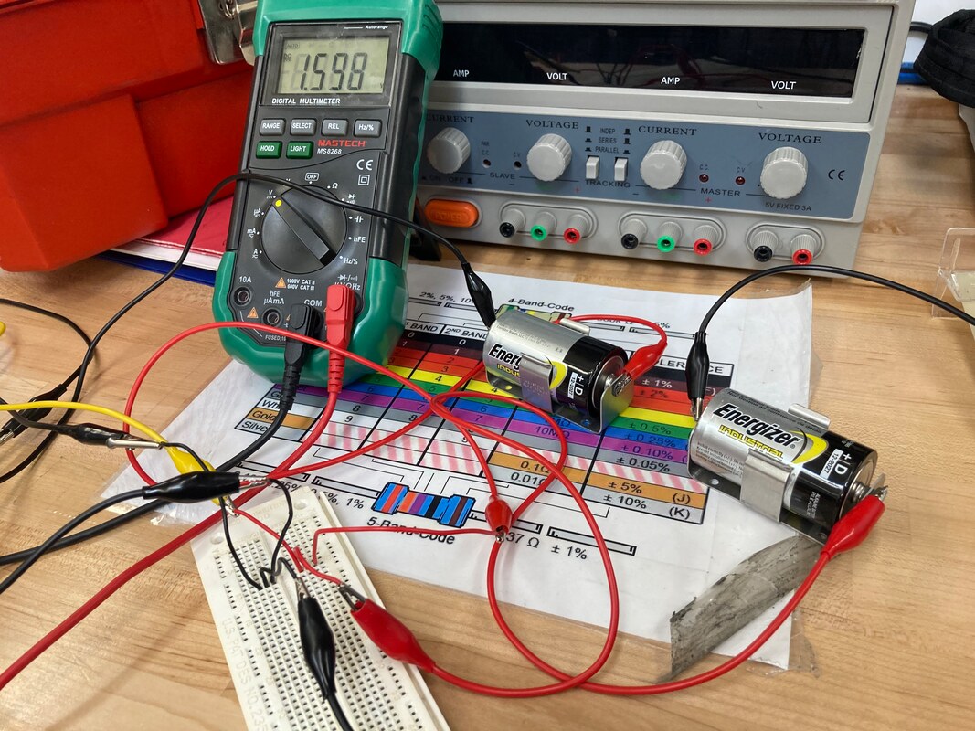
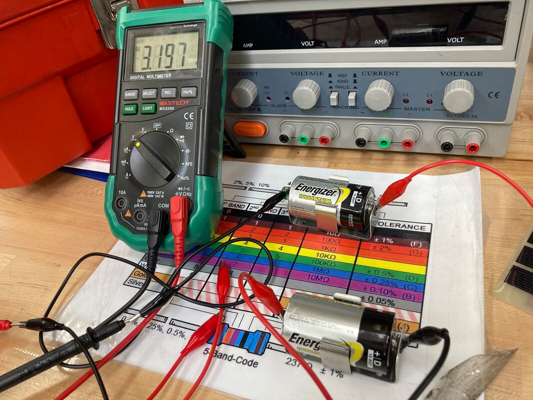
Next, we looked at our alkaline cells. Firstly, we checked the voltage of each battery. When we connected them to our multimeter, they measured to produce 1.6 volts each. So, when we hooked them in series, together they produced 3.2 volts. Now we no longer have a singular cell, we have a complete battery.
However, when we hook these batteries in parallel, the multimeter only read the voltage produced by one battery, which is around 1.6 Volts. Lastly, when we hooked the two batteries in opposed series, there seemed to be close to no voltage produced, which was around 2.6 mV, which may not have even been from the battery.
However, when we hook these batteries in parallel, the multimeter only read the voltage produced by one battery, which is around 1.6 Volts. Lastly, when we hooked the two batteries in opposed series, there seemed to be close to no voltage produced, which was around 2.6 mV, which may not have even been from the battery.

|
Lastly, we looked at the solar cells. We used the leads to hook it up to our multimeter to measure the voltage that it produced. Under the normal light levels of the room, it measured to produce around 1.6 Volts. When we prevented the room's light from hitting the solar cells, we saw that the voltage that it produced decreased.
|
Why:
This lab helps me understand how cells and batteries work in the real world. When the solar cells still produced voltage even though its not directly being hit by the light source, it reminded me of solar paneling and how they can produce voltage from the sun, even when it's raining or snowing- usually weather that block our view of the sun.
Lastly, Thinking about our alkaline cells, connecting them in series to make a battery really helped me understand how batteries are made, and why we always have our AA batteries connected together. We're adding power to the circuit by using multiple batteries to add applied voltage.
Lastly, Thinking about our alkaline cells, connecting them in series to make a battery really helped me understand how batteries are made, and why we always have our AA batteries connected together. We're adding power to the circuit by using multiple batteries to add applied voltage.
Lab 15: Switches and Switching Circuits
|
|
What:
For this lab we learned about different types of switches and learn how they operate in a circuit.
Types of Switches:
Types of Switches:
- SPST (Single Pull Single Throw)
- DPST (Double Pull Single Throw)
- SPDT (Single Pull Double Throw)
- DPDT (Double Pull Double Throw)
How:
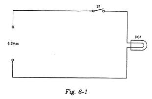
Looking at the picture on the left (Fig. 6-1), we have the basic kind of circuit. We have the positive side of our power supply hooked up to a SPST switch, a simple PBNO (Push Button Normally Open) connected to our miniature lamp. The lamp is then connected to the negative part of the power supply. When we hold down on the pushbutton, the lamp turns on.
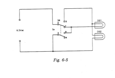
Looking at the picture on the right (Fig. 6-5), we see a complicated circuit compared to the first one. We have a DPDT switch connecting to lamps. When you look at the schematic above, you can see that the lights should always be turn on, however, it switches from coming from one pull side to two pull sides of the switch which means that we use the switch to switch the circuit itself from a parallel circuit to a series circuit. This affects the brightness of the miniature lamps.
Why:
The purpose of this lab was to learn about the different kinds of switches so we can use them properly.
Other Feedback
It's nice to know more than one types of switches and learn about them. It helps me to gain more knowledge about switches.
Lab 16: Ohm's Law
R1 |
R2 |
R3 |
R4 |
What:
For this lab, we learned what Ohm's law was and applied it by using fixed resistors to test the amount of current that would flow through a multimeter.
How:
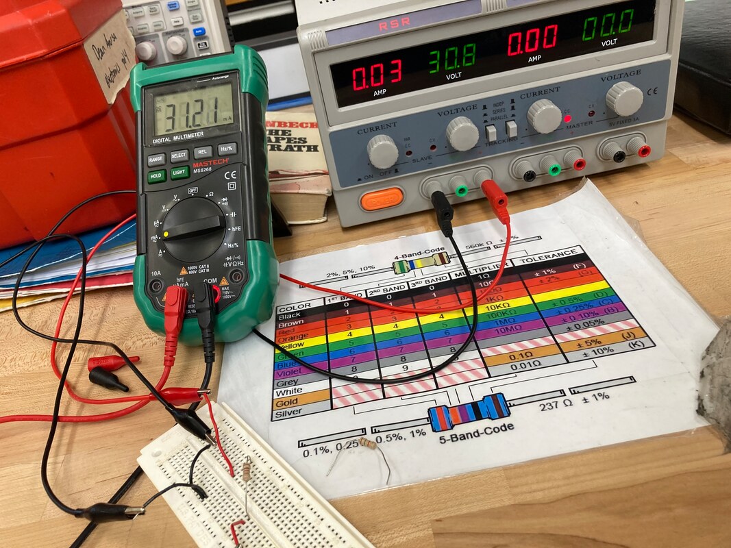
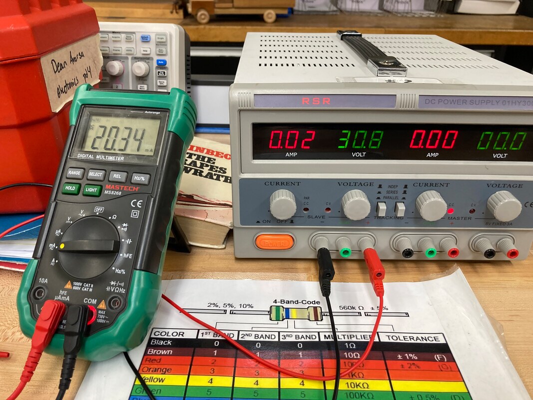
We used a fixed voltage of 30.7V for each experiment, and according to Ohm's law, current is the quotient of voltage divided by resistance.
For example, our 1 KΩ resistor measured to have 31 mA of current (R1). Converting to base units, that should be 30.7/1000, which would equal 0.0307 of current, very similar to our actual value of 31 mA.
Our strongest resistor, 10 KΩ, measured to produce a current of 3 mA (R4). When using Ohm's law to make the equation 30.7/10000, we get 0.003, which would convert to about 3 mA, which is exactly what was read on the multimeter.
Why:
The purpose of this lab is to learn about the uses of ohm's law, and learn how to use it. Ohm's law is a very helpful equation when working with electricity. It's helpful because you can determine how much of power, or amount of resistance you need in a circuits that you are making.
Other Feedback
I kinda like this lab because it helps me learn how to find the current, voltage, and resistance by using Ohms Law equation.
Lab 17:Power, Heat, Light (Watt's Law)
|
|
What:
We are tasked to learn the watt's law, and learn how to use it.
How:
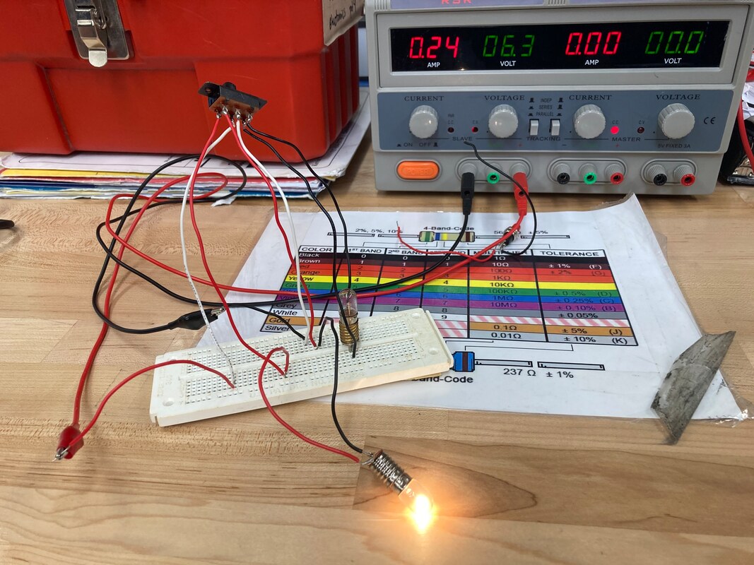
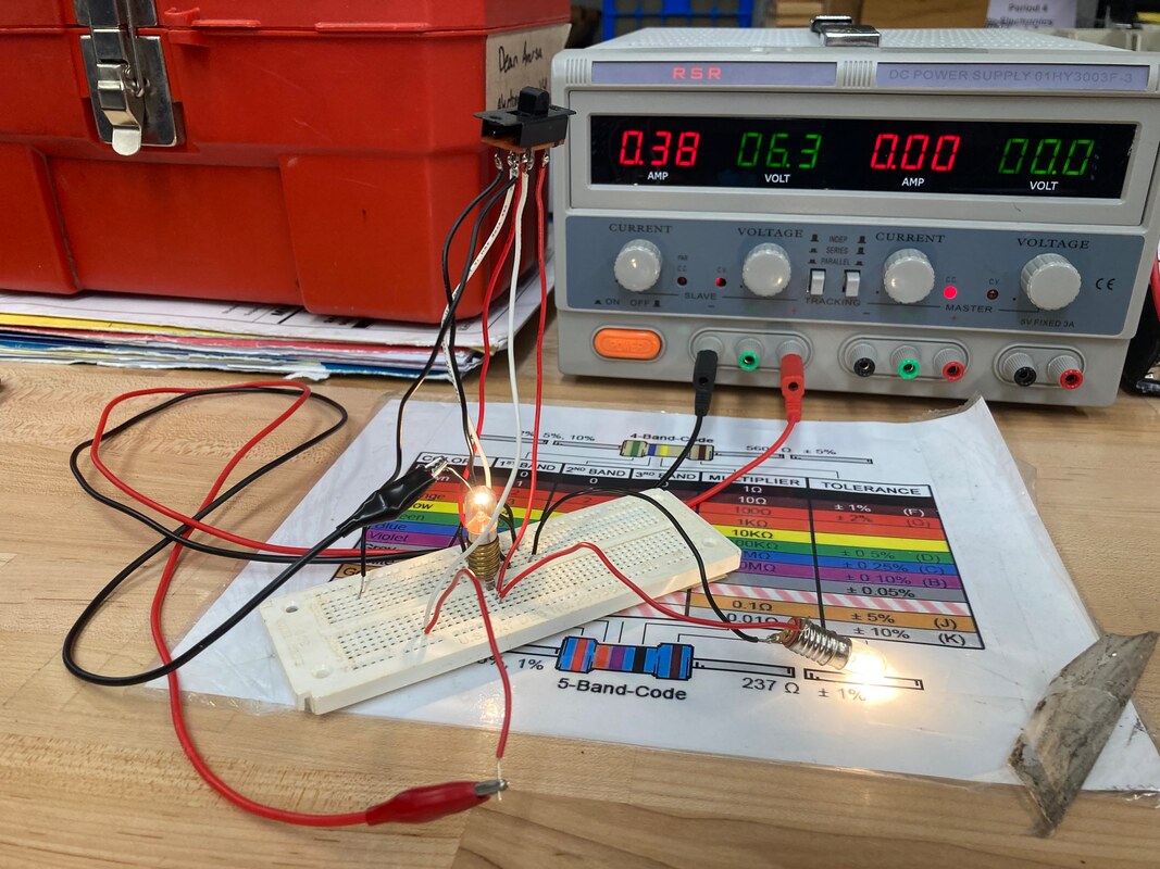
We used the Watt's Law formula to get the amount of watts a circuit would produce, providing it had 50 Ohms of resistance. We used voltage levels of 2V, 4V, 6V, 8V, and 10V. Then, we built a circuit and hooked in our voltmeter and ammeter to measure it ourselves. Our results looked very similar to the chart we used to calculate the current and power. Remember- the voltage and resistance stayed constant. Lastly, we used a light bulb which has a natural resistance of 6 Ohms- and varying levels of voltage to determine current, power, and resistance. from using E x I to determine P, power, and using E/I to determine R, resistance in Ohms. We found that the pattern is generally consistent.
Why:
The purpose of this lab is to learn about the relationship between volts, amps, and watts, and to learn how they not only affect each other, but how they affect electronic devices.
Other Feedback
This lab is a little challenging, it's because of a lot of components added to it to find Power. It also helps me learn how to use the watts's law to find the voltage and power of a light bulb.
Burglar Alarm Kit
|
|

|
|
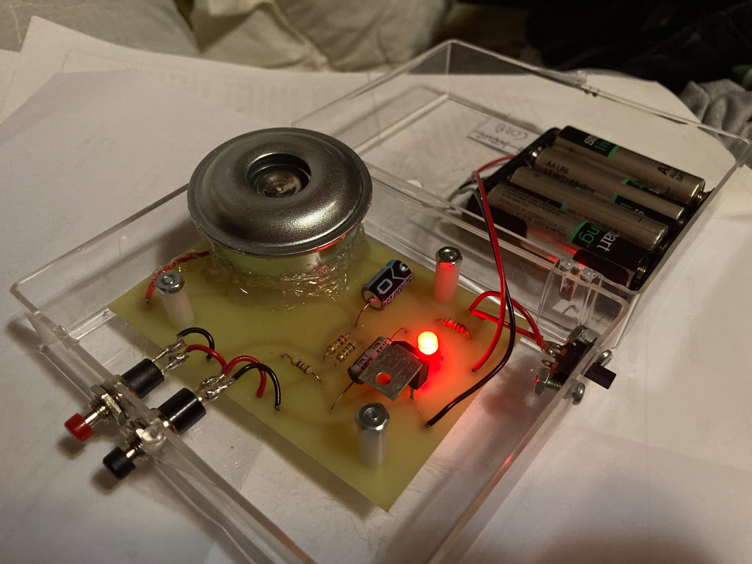
What:
In this project, Mr. Sieg gave us each a Burglar Alarm Kit and we have to put it in a circuit. The buzzer should goes off when a gate/switch is triggered closed/open (It depends where you hooked up).
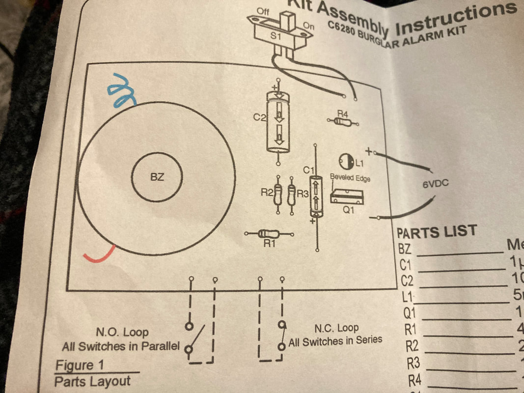
Parts List of the Kit:
1. BZ - Metal Horn Buzzer
2. C1 - 1uF Axial Capacitor
3. C2 - 100uF Axial Capacitor
4. L1 - 5mm Red LED
5. Q1 - 106D1 SCR
6. R1 - 4.7K Ohms Resistor
7. R2 - 20K Ohms Resistor
8. R3 - 1.5K Ohms Resistor
9. R4 - 1K Ohms Resistor
10. S1 - Slide Switch
11. Misc - Wire and PC Board
12. Transparent Plastic Box (Provided by Mr. Sieg)
How:
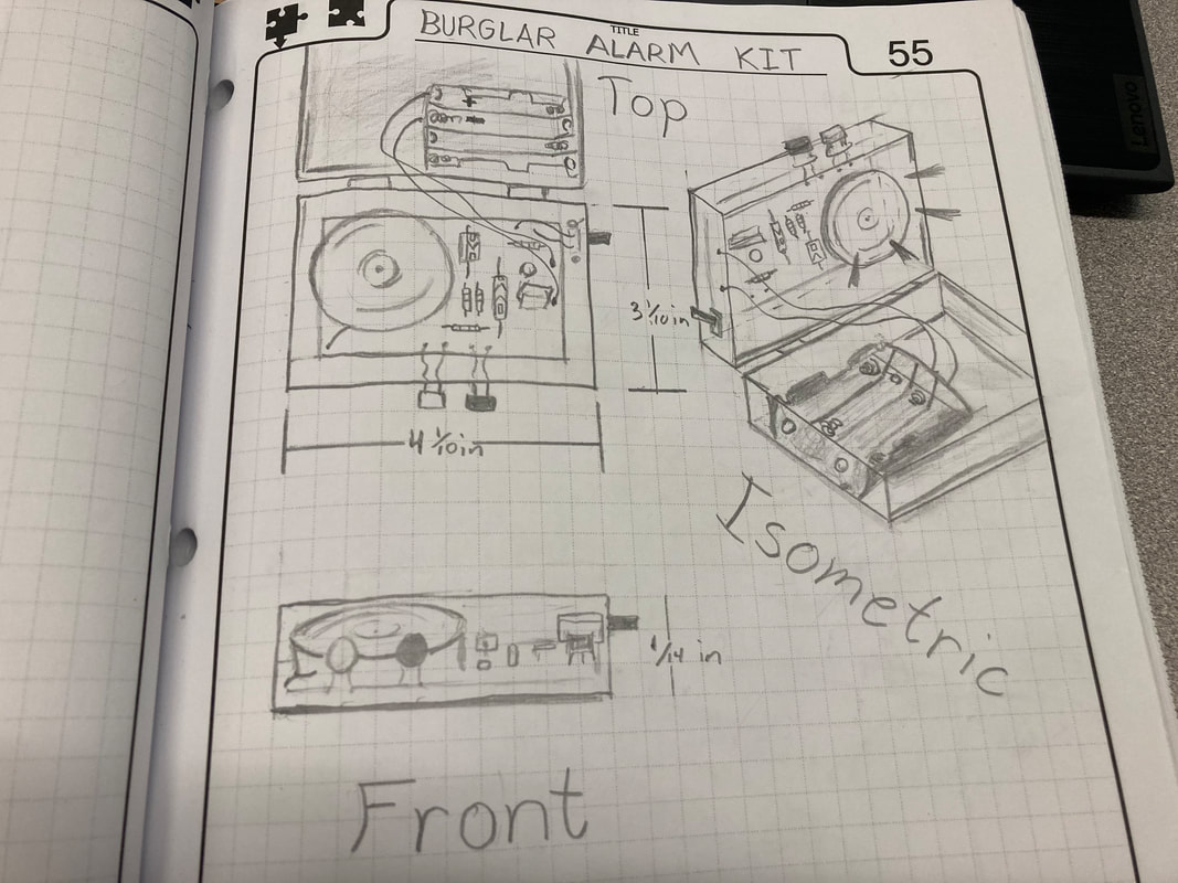
First, I connect all the components in the board, and make sure that they're in the right spot. Then, I start soldering the bottom carefully and cut the extra wire to make it balance, and tested the circuit. Once I got it working I begin to drilled a holes in a transparent plastic box using the drill press. For my burglar alarm kit, I drilled holes for the switch, then cut holes for the both push buttons (NO & NC), and drilled holes for my batteries holder purpose. lastly, I drilled three holes in my board to sit steadily in the board and not moving around in the box; drilled a hole for the horn buzzer to make it more louder. Finally, to make looks good I made an appropriate labels for the switch, push buttons, and for the buzzer.
Why:
We did this project to show what we've learned and test our knowledge in making a Burglar Alarm Kit. Also, to show that we know how to read a schematics and do the basic way of soldering to make a working circuit, and to demonstrate that we understand how electrical components are used and operate to make sure all the components in the board circuit is working properly.
Other Feedback
To be honest this project is really fun to make because we get to make our own circuit and make it work just based on what we've learned in this class over time. Even though I kind of struggle for making this work for the first two weeks I still able to finish strong and make it work. I'm proud of myself because Mr. Sieg Stated that my Burglar Alarm Kit is "One of the best kit I've seen so far."
